Example Device: DEBIX Model A
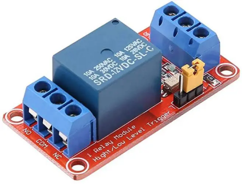
Relay Module
Overview:
lBy checking the schematic diagram of the relay module, it is clear that when the control terminal is high, the relay is engaged; and vice versa for disconnection.
Hardware Connection:
lConnect the control terminal of the relay module to Pin7 of the 40Pin double row pin (J2) of the DEBIX.
lConnect the VCC terminal of the relay module to Pin2 of the 40Pin double row pin (J2) of the DEBIX.
lConnect the GND terminal of the relay module to Pin6 of the 40Pin double row pin (J2) of the DEBIX.
Step:
1. Calculation of GPIO number:
Index = GPIOn_IOx = ( n - 1 ) * 32 + x
Take GPIO1_IO12 for example: Index = (1-1) * 32 + 12 = 12
2. Export GPIO and set GPIO properties.
lUse the calculated Index to export the GPIO:
echo 12 > /sys/class/gpio/export
lSet the GPIO as an output pin:
echo out > /sys/class/gpio/gpio12/direction
lSet the GPIO to be a non-interrupt pin:
echo none > /sys/class/gpio/gpio12/edge

3. Set the GPIO output level.
echo 1 > /sys/class/gpio/gpio12/value // output high level
echo 0 > /sys/class/gpio/gpio12/value // output low level
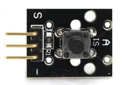
KEY Module
Overview:
lWhen the key is pressed, the output terminal outputs a low level;
lWhen the key is released, the output terminal outputs a high level.
Hardware Connection:
lConnect the output of the key module to Pin7 of the 40Pin double row pin (J2) of the DEBIX.
lConnect the VCC terminal of the key module to Pin2 of the 40Pin double row pin (J2) of the DEBIX.
lConnect the GND terminal of the key module to Pin6 of the 40Pin double row pin (J2) of the DEBIX.
Step:
1. Calculate the GPIO number in the same way as the relay module.
Take GPIO1_IO12 for example: Index = (1-1)* 32 + 12 = 12
2. Export GPIO and set GPIO properties.
echo 12 > /sys/class/gpio/export //export GPIO
echo in > /sys/class/gpio/gpio12/direction //set as input pin
echo none > /sys/class/gpio/gpio12/edge //set as a non-interrupt pin

3. Get the input level of the GPIO pins.
cat /sys/class/gpio/gpio12/value
![]()
Press the key and get the level again:
![]()
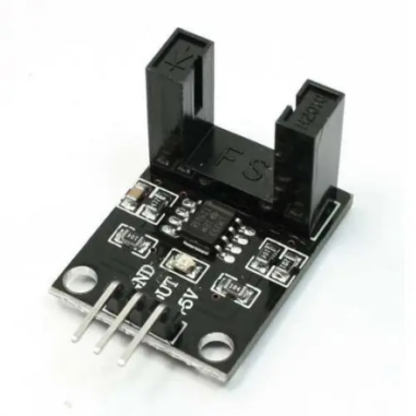
IR Sensor Module
Overview:
lWhen the IR pair of tubes is blocked, the output terminal will output a high level;
lWhen the IR pair of tubes is not blocked, the output terminal will output a low level.
Hardware Connection:
lConnect the output of the IR sensor module to Pin7 of the 40Pin double row pin (J2) of the DEBIX.
lConnect the VCC terminal of the IR sensor module to Pin2 of the 40Pin double row pin (J2) of the DEBIX.
lConnect the GND terminal of the IR sensor module to Pin6 of the 40Pin double row pin (J2) of the DEBIX.
Step:
The pin level changes can be queried using the steps in the Key Module section, and will be queried here through the application.
1. Calculate the GPIO number in the same way as the relay module.
Take GPIO1_IO12 for example: Index = (1-1)* 32 + 12 = 12
2. Export GPIO and set GPIO properties.
echo 12 > /sys/class/gpio/export // export GPIO
echo in > /sys/class/gpio/gpio12/direction // set as input pin
echo none > /sys/class/gpio/gpio12/edge // set as a non-interrupt pin

1. The test program is as follows:
#include <stdio.h>
#include <sys/types.h>
#include <sys/stat.h>
#include <fcntl.h>
#include <unistd.h>
#include <sys/ioctl.h>
#define GPIO_VAL_PATH "/sys/class/gpio/gpio12/value"
int main(int argc,char *argv[]){
unsigned char value;
int fd;
fd = open(GPIO_VAL_PATH, O_RDWR);
if (fd < 0){
return fd;
}
while (1){
read(fd,&value,1); // read the current level
lseek(fd,SEEK_SET,0); // always read the file header
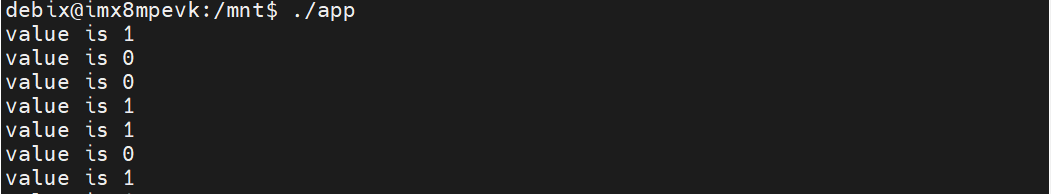
printf("value is %c \n", value); // reads the character
sleep(1); // delay1S
}
close(fd);
return 0;
}
When running the program on DEBIX, it can be seen that when the IR pair is blocked, the value read by DEBIX is "0":