DEBIX Camera Module is a camera module designed for DEBIX Model A/B. There are currently 3 camera modules available: DEBIX Camera 200A Module, DEBIX Camera 500A Module and DEBIX Camera 1300A Module.
Main features:
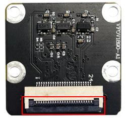
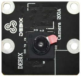
DEBIX Camera 200A Module
- 2 megapixels still resolution, 1600 x 1200/20fps video mode
- 76 degrees diagonal FOV, 60 degrees horizontal FOV, 50 degrees vertical FOV
- Fixed focus for default, could be changed to auto focus
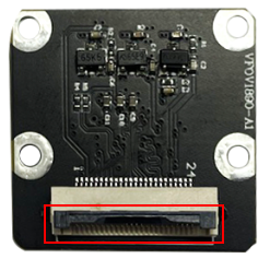
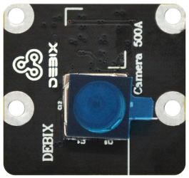
DEBIX Camera 500A Module
- 5 megapixels still resolution, three video modes: 2592 x 1944/15fps, 1920 x 1080/30fps, 1280 x 960/45fps
- 72 degrees diagonal FOV, 58 degrees horizontal FOV, 45 degrees vertical FOV
- Auto focus for default, could be changed to fixed focus
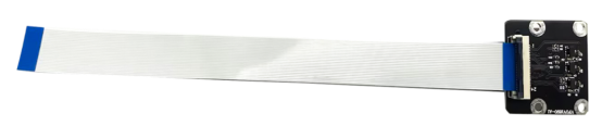
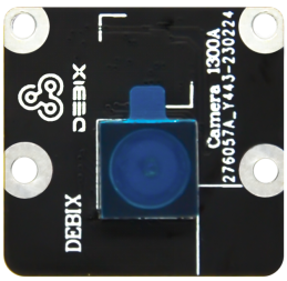
DEBIX Camera 1300A Module
- 13 megapixels still resolution, three video modes: 4208 x 3120/30fps, 3840 x 2160/30fps, 1920 x 1080/60fps
- 80 degrees diagonal FOV, 68 degrees horizontal FOV, 54 degrees vertical FOV
- Auto focus for default, could be changed to fixed focus
 |
 |
 |
|
Figure 1 DEBIX Camera 200A Module |
Figure 2 DEBIX Camera 500A Module |
Figure 3 DEBIX Camera 1300A Module |
| Parameter | Camera 200A | Camera 500A | Camera 1300A |
|
Still Resolution |
2 megapixels |
5 megapixels |
13 megapixels |
|
Video Mode |
1600 x 1200/20fps |
· 2592 x 1944/15fps · 1920 x 1080/30fps· 1280 x 960/45fps |
· 4208 x 3120/30fps · 3840 x 2160/30fps· 1920 x 1080/60fps |
|
Sensor |
GC2145 |
OV5640 |
AR1335 |
|
Sensor Resolution |
1616 x 1232 pixels |
2592 x 1944 pixels |
4208 x 3120 pixels |
|
Sensor Image Area |
2.83mm x 2.16mm |
3.67mm x 2.74mm |
4.629mm x 3.432mm |
|
Pixel Size |
1.75um x 1.75um |
1.4um x 1.4um |
1.1um x 1.1um |
|
Optical Size |
1/5” |
1/4” |
1/3” |
|
Depth of Field |
Approx 30cm to ∞ |
Approx 10cm to ∞ |
Approx 10cm to ∞ |
|
Diagonal FOV |
76° |
72° |
80° |
|
Horizontal FOV |
60° |
58° |
68° |
|
Vertical FOV |
50° |
45° |
54° |
|
Focus |
Fixed (default, can be changed to Auto) |
Auto (default, can be changed to fixed) |
Auto (default, can be changed to fixed) |
|
Focal Length |
2.27mm |
3.25mm |
3.52mm |
|
Focal Ratio (F-Stop) |
2.2 |
2.8 |
2.2 |
|
Maximum Exposure Time (seconds) |
/ | 390 | / |
|
Size |
25 x 24 x 8.85mm |
25 x 24 x 7.5mm |
25 x 24 x 7.7mm |
|
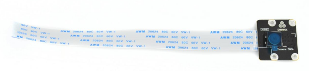
Flexible Flat Cable |
15cm |
||
|
Camera Lens |
|||
|
Lens Formats |
Raw/YCbCr4:2:2/RGB565 |
||
|
Lens Construction |
3P + 1IR |
3P + 1IR |
5P + 1IR |
|
TV Distortion |
<1.5% |
<1% |
<1% |
|
Thread |
M5 x 0.35P |
M6.0 x 0.35P |
M6.5 x 0.25P |
|
IR Filter |
650±10nm |
||
|
S/N Ratio |
TBD |
36dB |
37dB |
|
Dynamic Range |
TBD |
68dB |
69dB |
|
Power Supply |
· Core: 1.8VDC · Analog: 2.8VDC· I/O: 3.3VDC |
· Core: 1.5VDC · Analog: 2.8VDC· I/O: 3.3VDC |
· Core: 1.2VDC · Analog: 2.7VDC· I/O: 3.3VDC |
|
Power Consumption (Operating) |
100mW |
160mW |
270mW |
|
Temperature Range |
· Operating Temp: -30°C~ 70°C · Storage Temp: -45°C~ 85°C |
||
DEBIX Camera Module is composed of camera chip and lens. Camera 200A and Camera 500A lenses both contain 1 IR filter and 3 plastic lenses, while Camera 1300A lens consists of 1 IR filter and 5 plastic lenses.
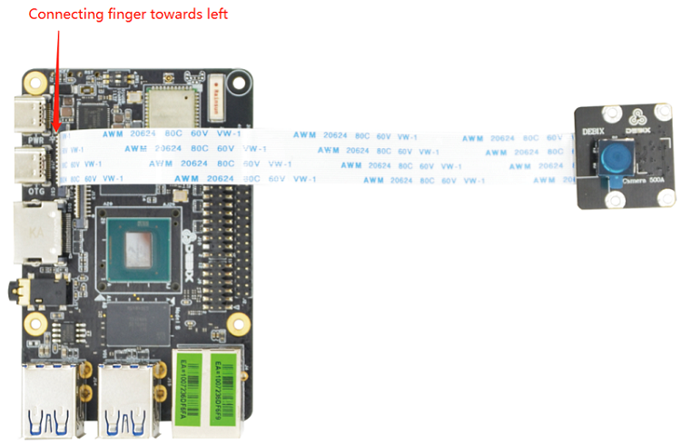
DEBIX Camera Module's 24-pin connection interface can be used to connect to the CSI interface of DEBIX Model A/B, or the 24-pin connection interface of camera adapter board for DEBIX SOM A I/O Board. The pin sequence is as shown in the figure:
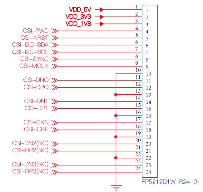
Figure 4
The interface is defined as follows:
| Pins | Definition | Description |
| 1 |
VDD_5V |
5V input |
| 2 |
VDD_3V3 |
3.3V input |
| 3 |
VDD_1V8 |
1.8V input |
| 4 |
CSI_PWD |
Power Control |
| 5 |
CSI_NRST |
Reset control |
| 6 |
CSI_I2C_SDA |
I2C data signal (controlled by I2C2) |
| 7 |
CSI_I2C_SCL |
I2C clock signal (controlled by I2C2) |
| 8 |
CSI_SYNC |
Synchronization signal |
| 9 |
CSI_MCLK |
Master clock input |
| 10 |
GND |
Ground terminal |
| 11 |
CSI_DN0 |
CSI Differential data channel 0 (-) |
| 12 |
CSI_DP0 |
CSI Differential data channel 0 (+) |
| 13 |
GND |
Ground terminal |
| 14 |
CSI_DN1 |
CSI Differential data channel 1 (-) |
| 15 |
CSI_DP1 |
CSI Differential data channel 1 (+) |
| 16 |
GND |
Ground terminal |
| 17 |
CSI_CKN |
CSI Differential Clock Channels (-) |
| 18 |
CSI_CKP |
CSI Differential Clock Channels (+) |
| 19 |
GND |
Ground terminal |
| 20 |
CSI_DN2 |
CSI Differential data channel 2 (-) |
| 21 |
CSI_DP2 |
CSI Differential data channel 2 (+) |
| 22 |
GND |
Ground terminal |
| 23 |
CSI_DN3 |
CSI Differential data channel 3 (-) |
| 24 |
CSI_DP3 |
CSI Differential data channel 3 (+) |